Hello Folks,
Several people have requested this and there is less than a month until the ARRL 10m contest so I figured I should get this out.
Based off the inspiration of several other hams and the calculations of the program Moxgen I was able to create a low-cost directional antenna for the 10m band. As we are finally climbing up solar cycle 25 I am pleased to report that 10m is becoming a very hot band to be on! Being somewhat financially constrained, portable focused, and unable to find a commercial solution for a 10m Moxon I set out to build my own.
First off the modeling is very basic as the heavy lifting has already been done by AC6LA and W4RNL (and of course Les Moxon G6XN) download this program and you can simulate any two-element, Moxon, you want. If you want to get more in-depth it will generate the EZNEC model for you Moxgen Program
From there you can input your wire size and desired frequency (Velocity factor due to wire insulation is not accounted for in the moxgen model for my 14AWG PVC insulated wire I noticed I needed to shink the antenna around 4-5% to achieve the desired resonance. Your results may vary). Once you have your numbers you can begin cutting wire. you should have three distinct pieces of wire, one reflector, and the two halves of the driven element.
The parts list for this antenna is intentionally limited:
4x 10ft fishing pole Link
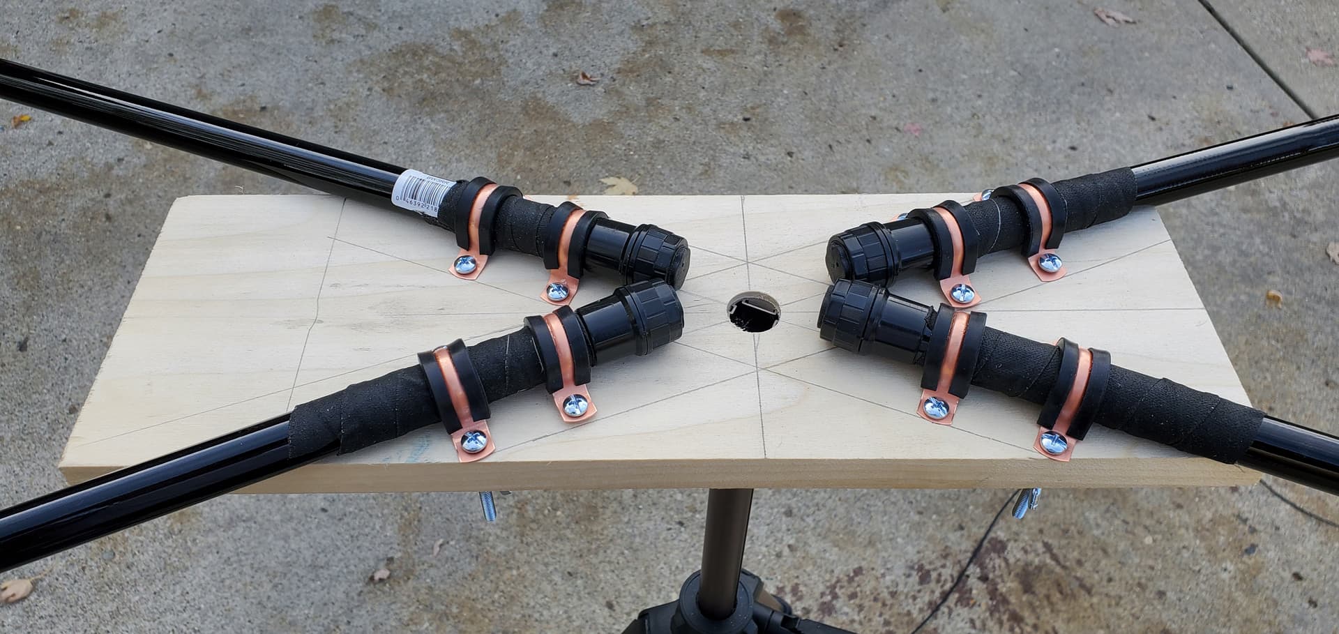
8x 3/4" CTS Pipe Straps Link
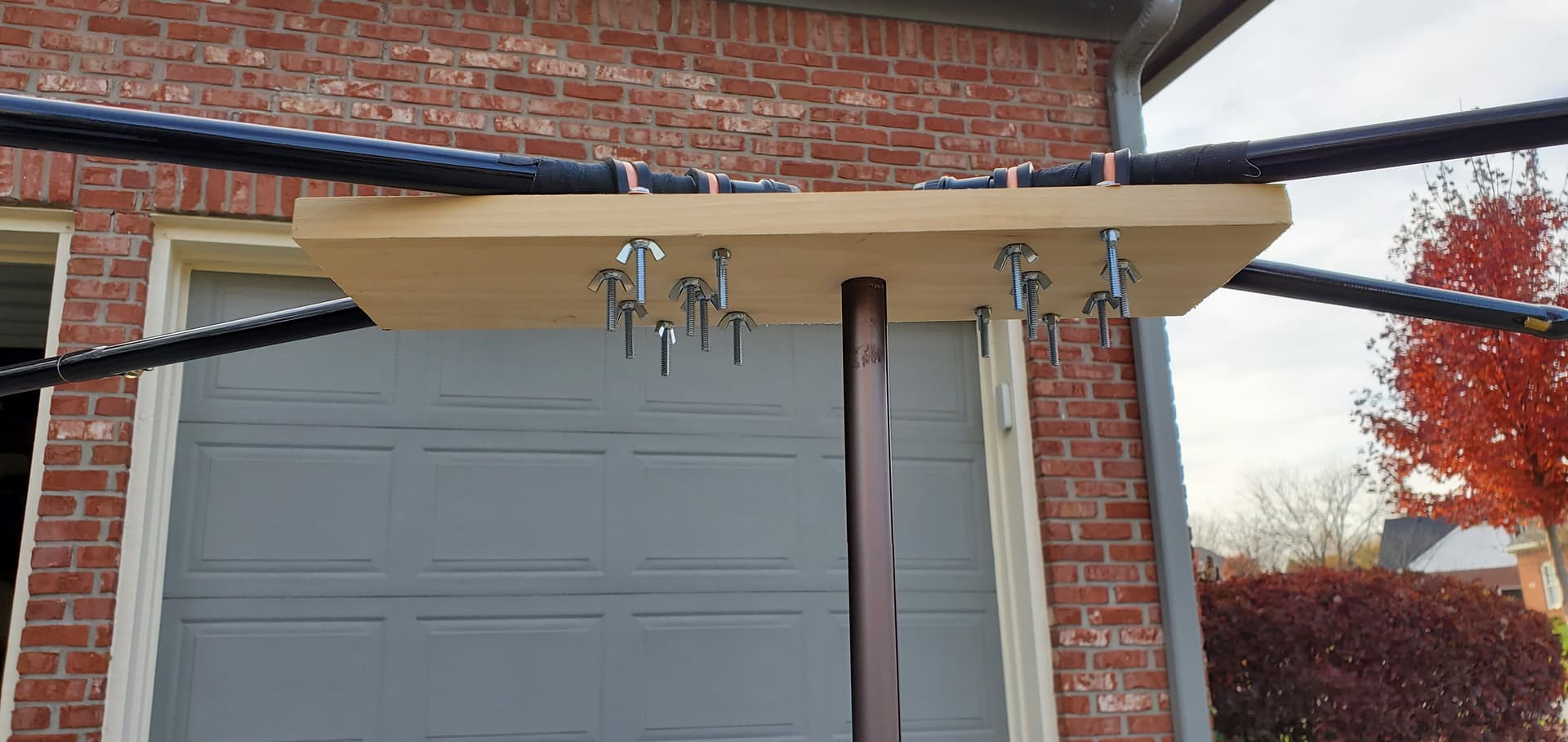
1x Baseplate, which can be any sturdy and light plank of wood or like material (I have seen others use plastic cutting boards). Mine was roughly 6"x18"x1" dimensions arent super critical as long as each fishing pole has two pipe straps holding it.
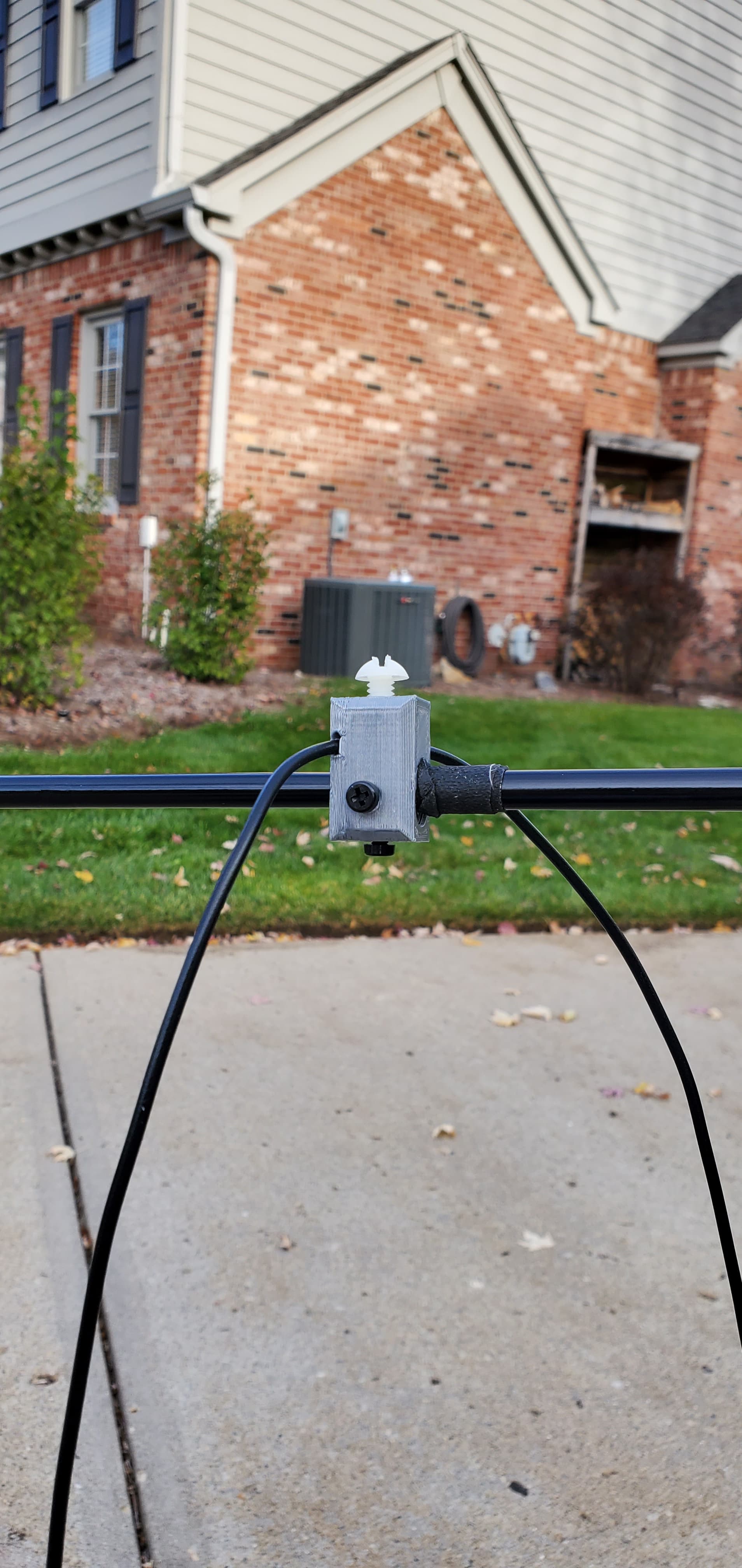
1x Balun feedpoint: convenient point to feed the wire antenna with coax. Since this is a balanced antenna you want to have a balun to convert the unbalanced coax feed to the balanced antenna. Specific balun used is not required as its what i had on hand. DIY baluns are easily done as well.Link
3D Print Link
2x Element spacers: not critical what this is made of except that it holds the driven and reflector ends at the specified distance (still experimenting at this time if this distance is also shrunk by 5%).
4x cable clamps: these slide onto the fishing poles and hold the wire at the appropriate tension. Set screws pin the clamps onto any point of the tapered pole and one screw is used to clamp the wire at the correct point of the antenna. Nylon or plastic screws are recommended so as to not impact antenna resonance. Link
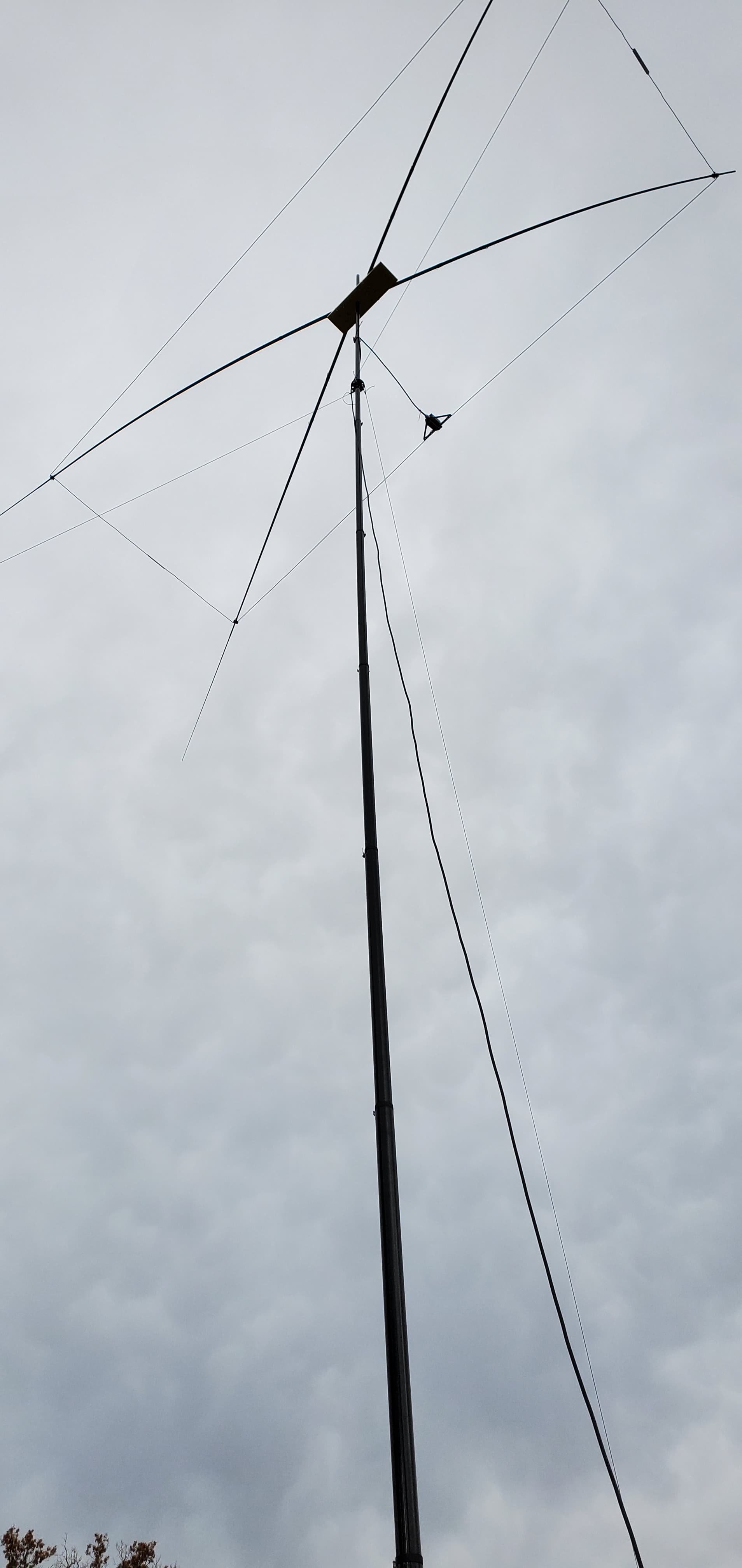
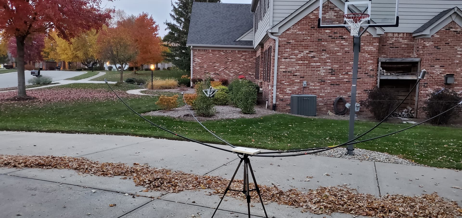
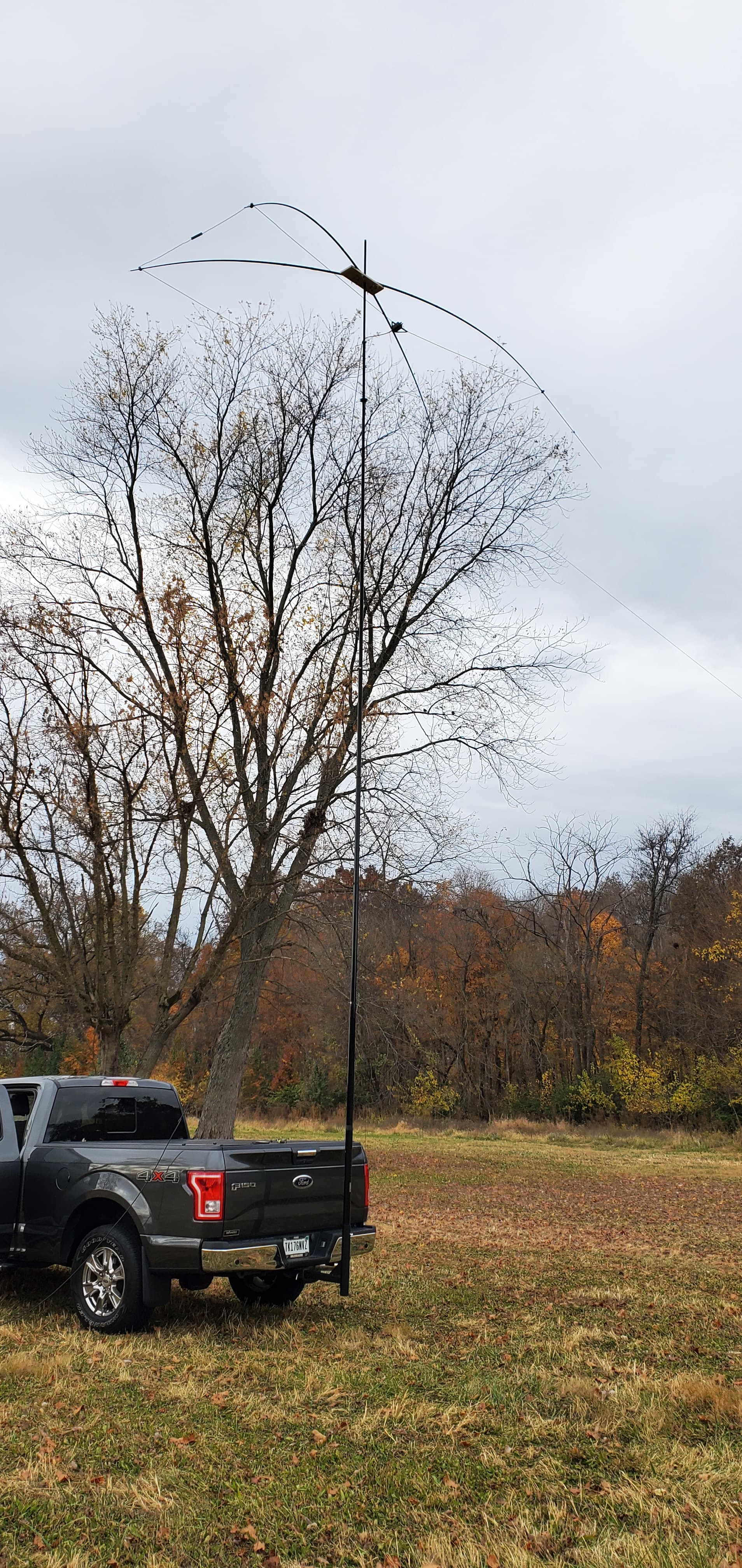
With these items in hand you mount the fishing poles to the baseplate in an X configuration using the pipe straps. Center the poles around a drilled hole in the middle of the baseplate that will be used to mount the antenna to your mast. The angle between each pair of poles should be 40 degrees. I used bolts and wing nuts to secure the pipe straps to the baseplate so it is easy to take the poles off and store them. I will also note that I wrapped the poles in friction tape at the base to prevent them from slipping around in the mounts.
Once you have your X assembled you need to measure the points along the wires that your cable clamps need to be and secure them. Then slide the clamps onto the pole (I currently have mine around 4" from the tip of the second largest segment) and tighen the set screws. Once you put all four corners on the fishing poles the antenna will naturally curl as the wires pull on the antenna. The poles seem to take the strain fine and you can adjust the clamps to decrease tension as needed.
From here it’s time to mount your antenna and tune the antenna with a VNA by trimming element lengths. For those that want to build this I will be around to assist as this isn’t the most complete instruction by any means.
Hope this helps